- Research article
- Open access
- Published:
Compound locomotion control system combining crawling and walking for multi-crawler multi-arm robot to adapt unstructured and unknown terrain
ROBOMECH Journal volume 5, Article number: 2 (2018)
Abstract
How to improve task performance and how to control a robot in extreme environments when just a few sensors can be used to obtain environmental information are two of the problems for disaster response robots (DRRs). Compared with conventional DRRs, multi-arm multi-flipper crawler type robot (MAMFR) have high mobility and task-execution capabilities. Because, crawler robots and quadruped robots have complementary advantages in locomotion, therefore we have the vision to combine both of these advantages in MAMFR. Usually, MAMFR (like four-arm four-flipper robot OCTOPUS) was designed for working in extreme environments such as that with heavy smoke and fog. Therefore it is a quite necessary requirement that DRR should have the ability to work in the situation even if vision and laser sensors are not available. To maximize terrains adaption ability, self-balancing capability, and obstacle getting over capability in unstructured disaster site, as well as reduce the difficulty of robot control, we proposed a semi-autonomous control system to realize this compound locomotion method for MAMFRs. In this control strategy, robot can explore the terrain and obtain basic information about the surrounding by its structure and internal sensors, such as encoder and inertial measurement unit. Except that control system also can recognize the relative positional relationship between robot and surrounding environment through its arms and crawlers state when robot moving. Because the control rules is simple but effective, and each part can adjust its own state automatically according to robot state and explored terrain, MRMFRs have better terrain adaptability and stability. Experimental results with a virtual reality simulator indicated that the designed control system significantly improved stability and mobility of robot in tasks, it also indicated that robot can adapt complex terrain when controlled by designed control system.
Background
Since disaster response robots (DRRs) have been used in Mt. Unzen in Japan [1], many kinds of robots with different functions have been developed, like snake robot [2], jump robot [3], one arm rescue robot [4], and so on. DRRs which have four sub-crawler are often used in disaster response work [5, 6]. This kind of robot has benefit at shrinking the size by lifting sub-crawlers to turn around in narrow space and stretching the size by rotating sub-crawlers downward to climb over obstacles [7]. Many DRRs has a mobile platform equipped with several sensors, hence these robots can perform tasks based on environmental information obtained from the sensors.
However, current DRRs have some problems in terms of balance between robot mobility and arm manipulation function. Most of DRRs just specialize in one of them, but both of them are important in disaster response tasks. In order to improve performance of DRRs as well as enable them to be deployed to more complex disaster sites, we have developed hydraulic-driven OCTOPUS (h-OCTOPUS), which has multi-DOF (degrees of freedom) four arms mounted on four sub-crawler robot [8, 9]. We then developed electrically-driven OCTOPUS (e-OCTOPUS) for especially indoor applications, as shown in Fig. 1. The structure of four-arm and four-crawler provides excellent mobility and task-execution ability, which are both important and useful functions for complex disaster response work.

Electrically-driven OCTOPUS (e-OCTOPUS), which has four crawlers and four arms disaster response robot
The most basic requirement for DRR is to reach the designated location. Thus, robot mobility should be considered first. The robot is required to have ability to move arbitrary environment in arbitrary conditions. Therefore, the mobility which should be improved basically includes the following two aspects.
-
Mobility in unstructured environment The robot should traverse complex geometric ground, such as rough terrain, unstable and unstructured ground, high step, and obstacles. To end this, the robot must have a suitable physical structure and a control system to provide stability and driving force to arbitrary directions, in particular, vertical upward.
-
Mobility in unknown (low-visibility) environment The robot should move even when the visibility for human operators and/or robot itself is quite low. In extreme environment with heavy smoke and fog, the vision sensors for localization, mapping, and navigation cannot obtain sufficient environmental information. Moreover, even when such vision sensors are broken, the robot keeps to move for continuing tasks or returning to the rescue base.
To realize these two requirements together, we proposed a compound locomotion method to integrate controls of crawlers and arms for robot moving. In this method, the crawler mainly drives the robot, and four arms assist the robot moving like a quadruped robot. This method can not only compensate the drawbacks of each locomotion method, but also enhance the advantages of each locomotion method.
Currently, many DRRs and construction machines adopt a crawler-type structure. TITAN XI [10] has four stronger legs and two crawlers, which can adapt different terrains by changing locomotion methods, such as walking on a slope using four legs or crawling on flat ground using two crawlers. However, there are no control method to combine the advantages of crawling and walking at the same time for TITAN XI. However, some robots adopt a leg mechanism that would be more suitable for irregular terrains [11]. Here, MAMFR has both crawlers and legs (arms), therefore it can move by using the crawlers, and moreover, improve the stability and mobility by making the arms contact with the ground to support the robot body like legs. The proposed compound locomotion combines the advantages of crawling and walking, and thus, the robot mobility would improve drastically. Moreover, the arm can grope environment, so simple but necessary terrain information for locomotion can be estimated, such as the height of obstacle and the terrain tilt angle, like human’s groping something in the dark (invisible situation).
Here, there are two essential technical issues to be solved to realize the compound locomotion method. The first issue is to integrate control strategies of legged robot and flipper-crawler robot, which are completely different with each other. The second one is to develop a method to explore the necessary terrain conditions by only using few vision sensors information. Laser range sensors are useful to obtain terrain information and robot position, which is called simultaneous localization and mapping (SLAM) system [12,13,14]. SLAM systems can describe the positional and simple postural relationship between the whole robot (robot body) and environment. But, it is difficult to describe the relationship between environment and every part of robot in detail, such as arm’s contact state. Moreover, in extreme situation such as fog and strong radiation, such sensors cannot work correctly, as stated above. The purpose of this study is to develop a new locomotion method which combines crawling motion using crawlers and walking motion using arms, for multi-crawler multi-arm disaster response robots.
The paper is structured in the following way: “Classification of locomotion modes” section explains the basic locomotion modes for multi-crawler multi-arm robots. “The advantages of CLM” section describes the basic requirements and functions of CLM, and “Requirements of CLM” section explains CLM and control system in detail. “Control system design for CLM” section then describes our experiments and setting. “Experimental setting” section explains the experimental results and analysis. “Results and discussion” section discusses the problems and improvement points in CLM. “Conclusion and future works” section summarizes our findings and discusses our future works.
Classification of locomotion modes
Multi-crawler multi-arm robots would provide flexibility for locomotion mode. According to the terrain state and collaborative relationships between the arms and crawlers, we can define several locomotion modes, namely, crawler crawling (CCM), arm walking (AWM) and compound locomotion mode (CLM), as shown in Fig. 2a–c.

Multi-crawler multi-arm robot OCTOPUS and its locomotion modes
Crawler-crawling mode (CCM)
This mode has been widely used by current DDRs. It adopts deformable crawlers to adapt disaster terrain and get over an obstacle, as shown in Fig. 2a. In this mode, robot can move at a relatively high speed and get over low-height obstacle. CCM can be used when the robot moves on flat terrain. The DOFs to be controlled are no more than 5 (4 DOFs for crawlers and one for robot moving direction), so CCM can be realized by manual or well-designed automated control system [15,16,17].
Arm-walking mode (AWM)
In this mode, robot walks like a quadruped robot [18, 19] on the ground, and the robot body is off the ground. The arms can be considered to be legs, as shown in Fig. 2b. Therefore, the arms should be power enough to support robot body. A large number of joints should be control at the same time according to certain rules (gait control rules), so autonomous control system is needed.
Compound-locomotion mode (CLM)
In this mode, crawlers and arms closely cooperate to perform tasks, as shown in Fig. 2c. During the moving process, crawlers will provide the main driving force. Based on the torque information obtained from sensors, the angle of flippers will be adjusted to adapt terrain in real time. Robot arms can support robot moving and keep balance. According to the robot posture and estimated terrains information, the joints on robot arms will be adjusted to keep the endpoints of robot arms (EPRA) contacting with ground. These contact points provide additional support for robot and make it owning larger stability margin and better mobility. If the terrain is known, arms can be used to support robot moving when necessary, such as when climbing high step. However, the terrain in disaster site is often unknown, so CLM makes the arms and crawlers keep cooperating when robot moving. Because more than ten joints need to be precisely controlled in each sample period. Thus, it is quite difficult to achieve CLM with manual control method. Only automatic control systems would be suitable in this mode. Theoretically, semi-autonomous control system combines the flexibility of human control and accuracy of autonomous control, and which can well adapt complex disaster sites.
The advantages of CLM
With the help of the multi-crawler multi-arm structure, robot controlled by CLM mode has better performance.
Better mobility
In CLM control mode, the robot will be driven by crawling (crawlers) and walking (four legs) at the same time. Therefore, compared with walking driven method, CLM has bigger traction to make robot move forward. And by the support of arms, CLM has stronger lifting force to make robot moving upward than crawling drive method. So, we can regard CLM will give robot more powerful mobility.
Wider use range
During robot moving, arms, flippers and some robot inner sensors (such as encoders and joint current sensors) can be used to explore and obtain the environment information. Therefore, even if in some extreme environments or accidents that caused environmental sensors cannot be used, CLM control mode also works. So, the use range of robot controlled by CLM will be expanded.
More stable locomotion state
As CLM integrate clawing and walking locomotion method, robot has more contact points with ground compared with separate crawling and walking. In view of the speed of DRRs in disaster site will not fast, robot stability can be described by using static stable parameters, called stability margin which consists of contact points between robot and ground. Because the contact points of CLM is more than separate crawling and walking. We can think CLM has bigger stability margin during tasks, that is to say, CLM has more stable locomotion state in tasks.
Requirements of CLM
As the terrain of disaster site will be unknown and uneven, it is dangerous to make robot running in such environment without taking any measures while making sure robot in safe and balance. To find these measures, we can learn from geese. During this kinds of bird flying in a certain formation, no leader tells other birds their right positions and postures to keep the shape of formation. In fact, the bird’s team does not need that. Each bird just needs to adjust its own position and posture according to the certain rules, and the flying formation can keep in a stable shape. These control rules may include the distance, angle or other things between that bird and other birds. This is one of the classic examples for distributed control, which can be used to control multi-robot systems in complex environment without complete knowledge of environmental information [20,21,22].
Structurally, it is not difficult to imagine that multi-arm/leg multi-crawler robot systems have better mobility performance by the cooperation of arms/legs and crawlers. However, because of the complexity of environment and insufficient information about the disaster site, it is really difficult to tell the right position of each arm and flipper using centralized control method which is popular in current robot systems. Thus, current control methods cannot realize the structural advantages of these robots efficiently in unknown environment. Consequently, we need a more simple, efficient and reliable control system with high adaptability to fully play the role of structural advantages for this kind of robots. The originality of this paper is to design such a control system, which we call CLM mode.
We transplanted distributed control form multiple robots to one robot in CLM control mode. The cooperation in CLM control mode is based on each part of the robot such as arms and crawlers. For distributed control, the most important part is to set control rules for each part. By setting suitable control rules for each arm and flipper, we can control OCTOPUS to get over obstacle and keep in balance in complex even if in unknown environment. In addition to OCTOPUS, other similar structure robots can also use this setting by changing the parameters. To build these control rules, some necessary information is needed, such as the key parameters (robot position, posture and stability margin) as well as the state of arms and flippers.
Almost no robot has a similar structure with OCTOPUS in the past, and there is no report about CLM. As mentioned before, there are several problems in the design of CLM. To realize this mode, we first clarify some basic requirements. Then, we design the compound control strategies for crawlers and arms.
Requirements of control system
On the basis of the analysis in the previous sections, when multi-crawler multi-arm robots work in unstructured and unknown disaster sites, the semi-autonomous control system for CLM should have the following capabilities.
-
Control system should have the capability to understand key parameters of surrounding environment, such as obstacle height and the distance between robot and obstacle.
-
Control system could monitor robot stable state in real time, and maintain the robot state to be stable by controlling joints appropriately. This is because work site may be irregular and slipping the endpoints of arms is unavoidable when contacting it to the environment.
-
Control system could monitor robot stability margin real time to avoid accidents.
To realize the above requirements, the control method for arms and crawlers should be well designed. The control rules of them will be detailed in the following content.
Preparation: coordinate systems
Figure 3 shows the main dimensions of OCTOPUS, which has the three main joints on each arm, called swing, boom and elbow respectively. The D-H parameters of an arm are listed in Table 1. According to D-H parameters and forward kinematics, we can easily get the following equations about \(x^{\prime},y^{\prime},z^{\prime}\), which are EPRA represented in joint coordinate system {J}, as shown in Fig. 3.

Main dimension of OCTOPUS (unit: mm)
To facilitate developing a control system, we define a coordinate system to describe robot state and the relationship between robot and environment, as shown in Fig. 4a, b, which is a normal right-hand coordinate system, and we call it robot coordinate system {R}. When the roll, pitch and yaw angles of robot are zero, {R} has the same directions with world coordinate system {W}. For calculating the coordinate of EPRA in \(\left\{ R \right\},\) we next need a coordinate translation from {J} to \(\{ R\}\). In Eqs. 1–3, if we build coordinates systems have same direction with {W} in each rotation axis, the positive direction of \(\theta_{1} ,\theta_{2} , {\text{and }} \theta_{3}\) can be got depending on the rules of D-H parameters. Take the left front arm as an example, assuming the position of left front EPRA (P1 in Fig. 4a) in {R} is (x, y, z) then,

e-OCTOPUS coordinate system
Terrain exploration (estimation of height of obstacle)
As mentioned before, terrain exploration not using vision sensors is one of the important ability of CLM. For OCTOPUS type robot, important three-dimensional (3D) environment information and robot state in environment can be obtained, through the arm’s position in robot coordinate system and robot posture which includes roll, pitch and yaw angles of robot. After four arms contacted ground, on the basis of each arm joint angle and forward kinematics, the 3D coordinates of four EPRA can be obtained. Then, the height difference \(H_{EST }\) between the endpoints of front arms and rear arms can be calculated, as shown in Fig. 4b. The terrain information can be obtained like follows. Note that the results of z1–z4 and z2 − z3 is the z coordinate of four EPRAs, which are called P1, P2, P3, and P4 respectively, as shown in Fig. 4a. σ1, σ2, and σ3 are three control parameters and can indicate terrain features, such as flat ground, upward or downward steps, respectively, and can be set according to actual condition.
-
Case 1: Flat terrain
\(\left| {{z}_{1} - {z}_{4} } \right| <{\sigma}_{1}\) and \(\left| {{z}_{2} - {z}_{3} } \right| < { \sigma }_{1}\).
Robot moves on a flat landscape. And the height different between four EPRAs is small than σ1.
-
Case 2: Upward step or slope
\({\sigma}_{1} < \left( {{z}_{1} - {z}_{4} } \right) < { \sigma }_{2}\) and \({\sigma}_{1} < \left( {{z}_{2} - {z}_{3} } \right) < { \sigma }_{2}\).
There is an upward step or obstacle in front of the robot. According to robot structure and driving force, robot has the ability to get over steps which height is lower than \(\sigma_{2}\).
-
Case 3: Downward step or pit
\(-{\sigma}_{3} < \left( {{z}_{1} - {z}_{4} } \right) < -{ \sigma }_{1}\) and \(-{\sigma}_{3} < \left( {{z}_{2} - {z}_{3} } \right) < -{ \sigma }_{1}\)
There is a downward step or a pit in front of robot. Robot has the ability to down steps which height is lower than \(\sigma_{3}\).
In addition, if robot is on a slope, the inclination angle of that terrain can be calculated.
where, T P is pitch angle of terrain in {W}, T R is roll angle of terrain in {W}, R P is pitch angle of robot, and R R is roll angle of robot. Here, we assume that there is an upward step in front of the robot (case 2), like Fig. 4b. According to four arms endpoints coordinate, the height of the step H EST can be estimated as
This height information is a very important parameter for getting over an obstacle, and it can be used to judge whether the robot has reached the top of the obstacle.
In addition to these three conditions. There are also many other kinds of situations that robot may meet. As we have mentioned before, semi-autonomous control system is suitable in CLM mode. Currently, if the robot system met the situations except for these three situation, autonomous control system will regard the terrains as “undetectable”, and operator can give control commends depend on the continuous feedback information.
Recognition of COG position of robot
When robot is moving, especially when getting over an obstacle, the robot COG position should be calculated in real time to identify the positional relationship between the robot and step. According to internal sensor data and mathematical model, the position of robot COG can be calculated. Due to the compact structure of OCTOPUS, the weight of the robot is concentrated in the chassis and the height of the COG is low. Therefore, when robot moving, the position of COG will not change too much. For the convenience of calculation, we assume that the position of robot COG is fixed when robot moving. For calculating the robot COG position in \(\{ W\}\), we need a calculation coordinate system \(\{ C\}\). It has the same coordinate origin with {R} and same directions with {W}.
To real OCTOPUS, the yaw angle of robot cannot be got. And in previous experiment in simulator, we found the change of robot yaw angel (robot moving direction) is very small in designed tasks (as shown in following parts: “rough terrain passing” and “getting over obstacle”). For the designed algorithms can be used in real robot, we assume the yaw angle is not change during these tasks. The pitch and roll angles of the robot can be obtained from inertial measurement unit (IMU) sensors, and these two angles can describe the relationship between \(\left\{ R \right\}\) and \(\{ C\}\), as shown in Fig. 5. P is the center point of two rear arm endpoints, according to forward kinematics, and the 3D coordinates RP (X R , Y R , Z R ) in {R} can be obtained easily. The coordinate of P in {C} denotes CP(X C , Y C , Z C ), and we can calculate obviously:

Calculation of robot COG height
In order to calculate CP from RP, we need a transition coordinate system \(\{ M\}\), and two rotation factors \({}_{M}^{C} R\) and \({}_{R}^{M} R\). For \(\{ M\}\), it has the same x-axis with \(\left\{ R \right\}\), and rotate A R degrees around x-axis. Thus, it is given by
Depending on the relationship between \(\left\{ R \right\}\), {M} and \(\left\{ C \right\}\), we can know the two rotation factors.
As we have known RP,
Thus,
Therefore, H1 can be calculated,
In the same method H2 can be calculated, thus the height of COG H is:
Except \(H\), the distance between an obstacle edge and front flipper S (as shown in Fig. 5) also can be calculated. When the robot starts to climb the obstacle, S equals to 0. The sampling frequency of our simulator is 50 Hz, basically, we can assume that the robot pitch angle \(R_{P } (i)\) does not change in one sampling period. The rotation speed of crawler is fixed in CLM, and the distance of robot moving is denoted by L in a sampling period. If we do not consider about sliding, thus,
To make this designed method be used generally, we need to consider about the posture of robot in 3D environment. For OCTOPUS, we assume the yaw angle is fixed, because the change of yaw angle cannot been got in real robot. For other systems which roll pitch yaw angle can be got precisely, this designed method and concept are also useful. The researchers just need to add other rotation factor in Eq. 11 to describe the change of yaw angle. Because it is simple matrix multiplication, we do not repeat it in here again.
Control system design for CLM
In every sampling period, control system detects robot state, then each part is controlled according to the following rules. In CLM, crawlers are main driving components, and they are controlled individually and without affecting arm’s state. Arms cooperate with crawlers to control robot moving. In the following sections, we chose two basic terrains and described the control method in detail.
Crawler controls
Many studies have proposed different autonomous or semi-autonomous control methods for multi-crawler DRRs for moving in irregular terrain. We designed a simple crawler control system on the basis of such control methods. When the robot moves forward, front flippers keep a suitable angle with ground to obtain the object information in the front of the robot. Before and after front flippers contact with obstacle or step, the torque applied to rotation axis of front flipper will greatly change. For example, before flipper contacts to obstacle, the torque is plus, but after that the data is minus. The force analysis of front flippers is shown in Fig. 6. Combined with arms explored terrain information, semi-autonomous control system can understand whether robot has closed to obstacle and what the robot should do in the next step. This part will be detailed in arm control section. For front flippers, the following cases may thus happen. Note that T′ and A′ are obtained front flipper torque and angle in the last sampling period, respectively. T0 is a torque threshold representing terrain condition. \(A\) is the flipper angle control command in the next control period.
-
Case 1: \(\left| {T^{\prime}} \right| < T_{0}\) (low torque)
Control rule: \(A = A^{\prime}\)
Measured torque will change in a certain range even if robot is running on a flat road, due to the vibration of robot. When robot is in this state, front flippers angle remain the same.
-
Case 2: \(\left| {T^{\prime}} \right| > T_{0}\) (high torque)
Control rule: \(A = A^{\prime} - \Delta A*(T^{\prime}/\left| {T^{\prime}} \right|)\)
ΔA is adjusting amplitude in each sample period. This parameter can be set according to the system sampling frequency and response time of flipper. When the robot is in this state, flippers will rotate depending on terrain state. For example, when robot encounters an obstacle, front flippers rotate up, while robot meets a pit, front flipper will rotate down.
-
Case 3: \(A^{\prime} > A_{0}\) (flippers in limitation position)
Control rule: \(A = A^{\prime} - \Delta B\)
A0 is front flipper limit value and ΔB is another adjusting amplitude for getting over obstacle. When robot is in this state, control system will consider there is an obstacle in front of robot. Combined with arms state, crawlers and arms will be controlled to get over obstacle, and this part will be detailed in later section.

Force analysis of robot front flippers
Arms and crawlers control in rough terrain passing
Conventional four-crawler robots pass through rough terrain by driving crawlers. Crawlers need to be close to the ground to provide drive force, therefore the posture of robot body is changed with terrain in real time. In CLM, the support of arm will reduce the load of crawlers, and crawlers do not need to completely fit the ground to drive robot. In addition, the support of arms will increase robot stability margin and can be used to adjust robot’s posture to assist crawlers to keep robot in balance. Due to the support of multiple crawlers and the distributed control strategy, four arms will adjust their positions and posture dynamically, depending on the robot and each part’s state. Therefore, the arms do need to strictly keep contacting with the ground all the time, slight slippage and off the ground are acceptable, and these will be adjust in next control periods. CLM thus enables robot to move more smoothly and stably.
-
1.
Robot gait design The four arms are considered as legs. For a quadruped robot, a suitable gait is needed in robot moving. There are several gait patterns can be used for quadruped walking, such as crawl gait, pace gait, trot gait and bounce gait [18]. Usually, when passing through rough terrain, the robot will not move fast, so crawl gait is thus suitable for controlling these four legs [23]. Except the support of arms, there are still at least four stable support points made by four moveable crawlers. In most cases, these contact points can make sure robot in balance. Therefore in CLM, we do not need to adjust robot center of gravity to one side [24] to keep robot in balance when transferring legs. Overall, the gait design of legs is more flexible in CLM. The designed gait for four legs is shown in Fig. 7. In this process, there are at least three arms support robot at any time. The polygon constituted by support points were illustrated in blue lines in Fig. 7. Four crawler are included in the blue polygon, which means that robot in CLM always has bigger stability margin than CCM.
Fig. 7 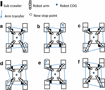
Robot gait in rough terrain
-
2.
Arm transfer Terrain would be unstructured in disaster sites. Thus, the arms should have the ability to adapt unstructured terrain. Every transferred arm should has suitable stop position, which enables arms to follow the designed gait and have proper contact force with ground. To realize that, we assume that the terrain is an extension of the explored ground. Depend on the robot structure and the size of each part, to maximize the stability margin of robot, the target coordinates of each EPRA after arm transfer in {R}. are specified as listed in Table 2. According to these coordinates and Eqs. 1–6, joints angle (θ1, θ2, θ3) of bot arm can calculated. In view of the expressions of results are ng, we will not show them in here.
Table 2 Designed coordinate for four arms transfer in {R} (unit: mm) -
3.
Trajectory plan of EPRA The current position of every EPRA can be calculated in real time, and its target position has been designed. In addition, the trajectory of EPRA from current to target position is also important. As mentioned before, one quite important function of the arm is to explore (grope) terrain information, especially the environment in front of robot. To make arm not be blocked easily during transfer and reach the designed position to explore the terrain, the position of EPRA should be high. Thus, we designed the following simple but effective EPRA trajectory. The motion of arm in transfer includes three phases, which are lifting arm (0–T1), rotating arm (T1–T2) and down arm (T2–T3), respectively.

The arm’s control depends on arm’s state and gait series. In lifting arm period, boom joint (θ2) and elbow joint (θ3) will rotate up from the current state, and swing joint (θ1) keeps still. After the boom joint reached the certain angle A B (for OCOTPUS, it is 0.6 rad for rear arms and − 0.6 for front arms. ΔB and ΔC are active for rear arm and minus for front arm), the first period (T1) is finished. After that, swing joint rotates forward, and the endpoint of arm will also rotate forward. Until the swing angle reaches A S (for OCTOPUS, it is 1.16 for rear arms and − 0.65 for front arms. ΔA is active for rear arm and minus for front arm), the second period (T2) is finished. After that, should joint keeps still, boom joint and elbow joint rotate down, until the endpoint of robot arm contacts with the ground, the last period (T3) is finished.
where θ1, θ2, θ3 are angle commands for each joint in the next sampling period, and \(\theta_{1}^{'} ,\theta_{2}^{'} ,\theta_{3}^{'}\) are the joints angle get from last sampling period. ΔA and \(\Delta B\) are adjust amplitudes for each joint and K can be set depending on the response situation of boom joint.
-
4.
Arm stop After inputting the target position, the arm will go along the specified trajectory until reaching the designed position. However, due to the complexity of disaster site, the arms always cannot exactly reach to the target points. For robot’s arms, if they collide with ground or obstacle, the torque of related joints will increase in a short time. During arm transferring, the arm will stop if the collision signal is detected. Basically, there are several cases may happen, which are shown as followings. Here, \(P_{i\_a} (x, y, z)\) is the actual stop point of EPRA and \(P_{i\_t} (x, y, z)\) is the target position that EPRA. ΔC and ΔD are the difference thresholds between setting value and real data, which can be set depending on the arm control accuracy.
-
Case 1: \(\left| {{P}_{{{i}\_{a}}} \left( {x} \right) - {P}_{{{i}\_{t}}} ({x})} \right| > \Delta {C}\)
This situation means that there are obstacles between the arm and target position.
-
Case 2: \(\left| {{P}_{{{i}\_{a}}} \left( {x} \right) - {P}_{{{i}\_{t}}} ({x})} \right| < \Delta {C}\) and \({P}_{{{i}\_{a}}} \left( {z} \right) - {P}_{{{i}\_{t}}} ({z}) > \Delta {D }\)
This means there are obstacles on the target position, and the EPRA stopped on the top of obstacle.
-
Case 3: \(\left| {{P}_{{{i}\_{a}}} \left( {x} \right) - {P}_{{{i}\_{t}}} ({x})} \right| < \Delta {C }\) and \({P}_{{{i}\_{a}}} \left( {z} \right) - {P}_{{{i}\_{t}}} \left( {z} \right) < - \Delta {D }\)
This means that there is a pit in the target position, and arm endpoint stopped at the bottom of this pit. In the last phase of transferring arm, EPRA will keep moving downward until control system detects stop signal or the arm joints reach the limit position. If arm still does not contact with ground when joints reach the limit position, it means where there is a deep pit. In this case, a new target point will be selected.
-
5.
Arm moving If the contact points between EPRA and ground are unchanged, arms will provide stably and continuously support for robot body, and it is benefit for robot balance. When robot is moving, the posture of robot will change with terrain. Thus, it is impossible for arms to keep contact points unchanged. In arm’s moving process, because the terrain is complex and unknown, even if the control systems has a certain ability to predict terrain, the changing of contact points in a small scale (slight slippage) is unavoidable. However, the multiple crawlers will keep supporting the robot body, and the arms posture and position will be adjusted to contact with ground in every control period. Therefore, the slippage of EPRA will not last long and not cause robot to lose balance. Thus, we can regard that the slippage is slight. To minimize the mobile range of contact points, one method is adjusting robot arm joints in real time according to robot current state and explored terrain information. In order to prevent robot arms being broken during EPRA’s slippage, two axes passive roller structure is used in OCTOPUS, as shown in Fig. 8. When robot is in state 1 and the contact points are PA1 and PB1 in robot coordinate system {R}. While robot in state 2, these two points can be represented as PA2 and PB2, as shown in Fig. 8. By considering the change of pitch angle and predicted terrain angle is small between two samples, we can predict state 2 using state 1 information. Usually, when robot is moving forward, the change of robot position along y-axis is small, so we assume that is remains constant. Therefore, the relationship between the contact points in two states is:For rear two arms:
$$P_{A2} (x) = P_{A1} (x) + L{ \cos }(T_{P} - R_{P} ),$$(22)$$P_{A2} (y) = P_{A1} (y),$$(23)$$P_{A2} (z) = P_{A1} (z) + L{ \sin }(T_{P} - R_{P} ).$$(24)Fig. 8 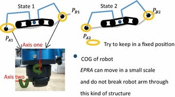
Robot moving state and arm end with two-axis

Moreover, for front two arms:
where T P is predicted terrain angle in state 1, R P is robot pitch angle in state 1, and L is crawler rotation distance between two samples.
Arms and crawlers control in getting over obstacle
Step is one kind of common obstacle in disaster sites. For DRRs, step climbing ability is one key performance index. Compared with conventional climbing method (just using crawlers and flippers), the CLM can greatly improve the climbing ability of OCTOPUS, at the same time improve the robot stability in climbing process.
Before front arms contacted with step, robot walks and adjusts arm position as the sequences in Figs. 7 and 9. In every sampling, control system calculates the height difference between front arms and rear arms endpoints. When one of its front arm touch the top of step, system will know there is a step in front of robot, like Fig. 9b. Robot will still move forward and adjust another one front arm to touch the “step”. After both front arms contact “step”, H EST can be calculated. If H EST is greater than setting value (such as the case 2 in terrain exploration), we can make sure that it is a real step in front of robot, as shown in Fig. 9c. After front flippers angles reach to the limit (85° in this robot), robot stops moving forward and adjusts its four arms posture for climbing step, as shown in Fig. 9d. Then, flippers (A and Aʹ, as shown in “Crawler control” part) and all boom joints (θ2 and θ ′2 as shown in Fig. 3) of arms rotate down to lift robot body. The control rules are shown in Eqs. 28 and 29.
where ΔE and ΔF are adjusting amplitudes for boom joints and flipper joints. L is the value calculated from robot structure (0.6 × 500, 500 is the length of robot body). At the same time, by the friction force generated from crawlers and step, robot can move forward slowly, as shown in Fig. 9e. In this step, we do not try to keep the position of the endpoint of arms consistent. This is because the pitch angle of the robot changes rapidly between two sampling period, and robot has enough time to adjust each joint angle (such as boom joint should move 5° in one sampling period 0.02 s). When robot COG height (H in Fig. 6) is higher than estimated step height (H EST in Eq. 9) and the moving distance (S in Fig. 5) reaches set value (0.3 m, depend on robot structure shown in Fig. 3, this value can keep robot in stable state on the top of step). And then, the flippers and arms will be released, like Fig. 9f–h.

Sequence of robot climbing step in CLM
Experimental setting
In this section, we describe the implementation of the proposed system and evaluation using a virtual reality (VR) simulator [8]. VR simulator can obtain large number of useful parameters. In addition, well designed simulator can verify control strategy quickly while consuming less cost and time. Before the effectiveness and safety of our proposed control system is confirmed, experiment using real robot would be dangerous. The e-OCTOPUS in VR simulator has same configurations with real robot, such as size, color, power, and weight.
Control system and hardware
The robot system mainly consists of control interface, upper computer, on-board computer, and e-OCTOPUS, as shown in Fig. 10. The specification of e-OCTOPUS is listed in Table 3, and the main dimensions of robot are shown in Fig. 3. Control interface includes joysticks and monitors. Operators input commands from four 7-DOF joysticks and four pedals. Visual information obtained from environment cameras or in-vehicle cameras can be displayed on two 42-in. monitors. Joysticks and pedals are connected with AD boards, while robot controller can read operator input form AD boards. The VR simulator and robot controller run in an upper computer with Linux operation system, and they were developed based on the open source softwares (ROS and GAZEBO). For the safety reason, a semi-autonomous control mode (one operator) and a full manual control mode (two operators) are integrated into robot control. Usually, the semi-autonomous control system is executed, and two operators can take over the control authority of robot when necessary. In semi-autonomous control system, the operator just inputs move direction, and semi-autonomous control system will automatically control robot to realize this order. The upper computer communicates with on-board computer through TCP/IP protocol at 50 Hz frequency. After robot-state information has been collected by on-board computer, it will be sent to the upper computer. Combined with input of operator, the detail control commands will be sent to on-board computer.

Robot system frame
Tasks setting
The aim of our proposed CLM and control system is to make MAMFRs like OCTOPUS have better mobility and terrains adaptation capability in extreme environment. Thus, the following experiments were designed by mainly focusing on these two aspects.
-
Getting over obstacle (test for mobility in unstructured environment) To facilitate comparison and analysis, we simplified the obstacle into step. The robot that can get over higher step has better obstacle get over capability. For testing CLM control mode, in this experiment, robot needed to finish three fundamental tasks in disaster response works, respectively, climbing a one-terrace step, climbing a two-terrace step from the front and climbing a two-terrace step from the side. According to the structure of OCTOPS, as shown in Fig. 3, OCTOPUS can climb the step which height is lower than 250 mm (the length of flippers) without using arms. Thus, we set the height of those steps are 400 mm [8], which is more than twice as steps in residential areas. Two locomotion modes (CCM and CLM) were used to get over one-terrace step, and CLM mode also be used to execute the other two tasks introduced above. For CCM, robot is manually controlled by two operators according to the sufficient feedback visual images. But for CLM, just one operator input move direction based on an image got form in-vehicle camera (the image shows the environment in front of robot), and CLM control system knows nothing about the environment in advance.
-
Passing through rough road (test for mobility in unknown environment) In this experiment, a 500 mm height concrete block was in the way of robot moving forward. The distance between robot right side and concrete block was about 10 mm. Some robot arms would collide with this obstacle and automatically adapt it. These information is also unknown by control system.
Results and discussion
According to the experimental aims, we analyzed the results from the following aspects.
One-terrace step getting over capability
Figure 11 shows the locomotion sequence of OCTOPUS in two locomotion modes. By the help of environment cameras in simulator, operators can sufficiently understand robot state and the environment around robot. They also can estimate the height of step and the distance between robot and step from the feedback images information. However, in semi-autonomous control method for CLM, control system is totally unaware of these information. The information it used completely comes from sensors amounted on robot, which are same as real robot. So for semi-autonomous control system, robot runs in an unstructured environment.

Two locomotion methods
CCM and CLM were compared in our experiment, as shown in Fig. 11. The robot was used as a conventional multi-crawler robot in CCM, arms were not been used when climbing step.
Figure 11a shows robot’s original state, every joint’s angle of robot is zero. Figure 11b indicates the locomotion sequences of robot in CCM. Two skilled operators manually controlled the robot, and they can obtain robot state information by observing monitor and communicate with each other to cooperatively control robot. We hope the arms will not contact with the ground during the experiment of CCM mode. In real world, the violent collisions between robot parts and ground may break robot, and therefore we should avoid these kind of collisions. In consideration of the collision is inevitable if all of the four arms in lower position, we lifted rear arms during our experiment. Because the front arms will not collide with ground, to reduce the interference of COG position caused by lifting arms, we keep the front arms in the original positions. Figure 11c shows the locomotion sequences of robot controlled by semi-autonomous control system based on CLM. Just one operator controlled robot movement direction, while the gait adjusting and step climbing were automatically controlled by system. Both of CCM and CLM were tested five times.
In CCM, operators had tried their best but robot cannot reach the top of step in all experiments, and this resulted that the success rate was 0%. Basically, we can regard that 400 mm step exceeds the crawler climbing capability of OCTOPUS. However, for CLM, the success rate was 100%. Figure 12 shows robot pitch and roll angles in two experiments. Two operators tried twice to climb step in CCM, but robot cannot finished the task and turned over, as shown in Fig. 11a4. But for CLM, by the assist of arms, OCTOPUS can climb 400 mm step easily, and the biggest pitch angle of robot just reached 0.6 rad. The roll angle of robot controlled by CLM mode do have too much change during task, the biggest roll angle is 0.03 rad. Compared with CLM control, the roll angle of robot in CMM control mode is relative big, which reached − 0.14 rad, however, this angel will not cause robot loss balance.

Pitch angle of robot in two modes
Compared with CCM, CLM has better obstacle getting over capability in unstructured environment, it takes full advantage of the structural characteristics of MAMFRs, and turns it into a kind of functional superiority. In CLM mode, arms need to be adjusted to follow robot moving, and thus, so compared with CCM, the robot speed is slower.
Robot stability in getting over one-terrace step
While robot is moving, by means of analytic geometry, the stability margins of robot can be calculated. Figure 13 shows robot stability margins in two experiments. The smallest SM of robot in all process was 0.15 m. According to the structure of robot, this SM is quite big. It is clear that the robot running in CLM has a larger margin in whole process. Especially when robot was climbing step, the support of arm can improve not only robot climbing ability, but also stability.

Stability margin of robot in two modes
In CLM, the angle of each joint in robot will change with robot moving to adapt terrain. The corresponding joint (i.e., swing, boom and elbow as shown in Fig. 3) in four arms almost has the similar change rules. Thus, in this part, we just analyze the change rule of right front (RF) arm and right rear (RR) arm. Figure 14 shows the joints change of RF and RR arms during robot walking on ground and climbing step. There are six phases in this process which corresponding to our design as shown in Fig. 9. The first phase is initialization. Crawlers and four arms contact ground to support robot like a four-legged robot, as shown in Fig. 14 (phase A). With robot moving, to keep the stability of contact points, all of the joints in arms would be adjusted in real time, as shown in Fig. 14 (phase B). Phase B1 means that RR arm was adjusting its posture to transfer the endpoint to a new contact point with the ground, and B2 means after RF arm reached a new contact point, the joints in RR arm will be real time controlled to follow the moving of robot body (refer to the arm moving section). In phase C, RR arm was stopped because robot front arm had contacted with the step, and RF arm was waiting for the posture adjustment order. Phase D shows RR arm was adjusting its posture for preparing to climbing step, and phase E indicates arms were assisting robot to climb step. In the last phase F, robot COG reached a suitable position, and robot released its flippers and arms to make robot stop steadily on the top of step.

Joints angle of robot RR and RF arms in task
It also can be found in Fig. 14 that not all the joints meet the set rules. Such as depend on the Eqs. 19–21, the value of θ2 should be 0.6 rad at t = T2. But, the value of θ2 in Fig. 14 is 0.7. We think it is caused by the response speed of robot boom joint. It is a half-closed loop control method for each joint’s angle. We send the data to joint’s controller, and the controller will use a closed loop control method to execute this commend. The communication frequency is 50 Hz in this simulator, so the joints should finish every command in 0.02 s. Through the PID of each joint has been optimized, the response speed is still not fast enough. Such as when the control command is 0.6 rad, the data of encoder is 0.55, therefore the final angel of boom is big than setting value (0.6 rad).
Getting over two-terrace step form the front
Except for one-terrace step, CLM control mode also been tested in a two-terrace step environment, the total height of this step is also 400 mm. The locomotion sequence is shown in Fig. 15. It is clear that robot can complete this task easily when OCTOPUS is control by CLM mode. Figure 16 shows the roll pitch angles and stability margin of robot in this task. Compared with the data obtained from in one-terrace task, the maximum pitch angel is smaller (0.59 rad), and the minimum stability margin is bigger (0.17 m). We think that is because two-terrace step has two edges, and they can provide additional support. Basically, if the total height is same, multi-terrace step is more easily got over.

Climb two-terrace step from the front using CLM mode

Key parameters during climbing two-terrace step from the front using CLM
Getting over two-terrace step form the side
In real disaster response works, the objects under left side and right side of robot do not always have the same height. Therefore, robot should have the ability to get over asymmetric obstacles, we simulated this situation in our simulator. In this task, robot needed to get over a two-terrace step from the side, the locomotion sequence is shown in Fig. 17. Because the heights of terrace under left side and right side crawlers are not same, so the arms and flippers of robot should adapt the terrain separately, as shown in Fig. 17(5)–(9). Figure 18 shows the key parameters of robot during this task, because the asymmetric terrain, robot has the biggest roll angle during this task, which reached − 0.25 rad, however, the pitch angle do not have too much difference with other two tasks. Due to this reason, the smallest stability margin of robot in this task is just 0.07 m, which is obviously less than the smallest margin in other tasks.

Climb two-terrace step from the side using CLM mode

Key parameters during climbing two-terrace step from the side using CLM
OCTOPUS controlled by CLM mode can adapt the designed three most fundamental scenarios. Basically, we can regard robot will adapt more other different terrains such as slopes and irregular terrain.
Robot terrain adaptability
Figure 19 shows the robot locomotion sequences that robot RF arm collided with an obstacle and automatically adapted it. The angle of joints in RF arm and elbow torque are shown in Fig. 20. In phase A, robot moved forward, arms transferred and moved with robot motion. After arm contacted with obstacle, the torque of elbow joint would reach to the setting value as shown in Fig. 20. When system detected this, all of the joints in that arm stopped in this sample period, and arm state moved to arm moving phase from the next sample period. In Fig. 20, robot RF arm met the obstacle at t1, and moved on the top of this obstacle in phase B. After that, left the obstacle top and contact with the ground at t2, and then it was normal arm transfer and moving phases, which are shown as phases D and E in Fig. 20b. In short, depending on sensor information and robot mechanical characteristics, arms can well adapt unknown terrain in CLM.

Robot locomotion sequences for adapting unknown terrain

RF arm contact with obstacle and ground
Discussion
Compared with previous researches, the new locomotion method CLM has less dependency on environmental information obtaining sensors. It fills the gap that control DRRs in extreme environment without enough environmental sensors. Basically, OCTOPUS can finish the evaluated tasks under CLM control mode. Except that the advantages we have talked about in above, there are also some things could be improved. Firstly, the time efficiency is low. We find that the spending time of CLM in tasks is longer than conventional control method, and we think it is caused by low arms moving speed, because to adapt robot gait, crawler speed cannot be too high. In principle, crawler and wheeled robots have higher speed than quadrupled robots [18]. This is one of the disadvantages of CLM. Secondly, the physical and mathematical model is relatively simple. There are still some complex terrains and special cases that we did not consider in this paper. Thirdly, the control method is designed for four-arm four-crawler robot, for other kinds of multi-arm multi-crawler robot, the control algorithms should be changed depend on the features of robot. But the control ideas and methods are same. At last, the slippage of crawler and arms should be comprehensively considered, because it may cause recognition error.
Conclusion and future works
This paper addressed a locomotion control system based on CLM for simplifying the control of multi-arm multi-crawler robot and improving its mobility and irregular terrain adaptation in unstructured environment. Some key problems and the corresponding solutions were proposed. In addition, the related mathematical models were built, and control system for CLM was developed. Finally, this control system was verified using a VR simulator. Compared with manually control CCM, semi-autonomous controlled CLM has better mobility and stability in unstructured environment. Through the mathematical model and robot structure characters, some simple but important parameters can be calculated. Experimental results also shown that OCTOPUS has the ability to adapt unknown terrain in CLM. CLM combines crawling and walking locomotion mode. This is our first attempt, and we understand the method presented in this paper is not perfect. In the future work, we will verify this control mode in real robot and optimize our mathematic model, in addition, we also want to build a more reasonable evaluating system to comprehensively study this kind of locomotion and combine other terrain exploration method to further improve robot control performance. We also try to build an integrated control system which include CCM, AWM and CLM control modes to make robot adapt different situation. Due to the limit of simulator, not all the import functions and indexes about robot could be tested, so we will do more experiments using real robot.
References
Ban Y (2002) Unmanned construction system: present status and challenges. In: 2002 International symposium on automation and robotics in construction. pp 241–246
Kamegawa T, Yamasaki T, Igarashit H, Matsuno F (2004) Development of the snake-like rescue robot “KOHGA”. In: 2004 IEEE international conference on robotics and automation (ICRA). pp 5081–5086
Tsukagoshi H, Sasaki M, Kitagawa A, Tanaka T (2005) Jumping robot for rescue operation with excellent traverse ability. In: 2005 IEEE/RSJ int. conf. intelligent robots and systems (IROS). pp 841–848
Carey W, Kurz M, Matte D (2012) Novel EOD robot design with dexterous gripper and intuitive teleoperation. In: 2012 IEEE international conference on world automation congress. pp 1–6
Okada Y, Nagatani K, Yoshida K (2009) Semi-autonomous operation of tracked vehicles on rough terrain using autonomous control of active flippers. In: 2009 IEEE/RSJ international conference on intelligent robots and systems (IROS). pp 2815–2820
Nagatani K, Yamasaki A, Yoshida K (2008) Semi-autonomous traversal on uneven terrain for a tracked vehicle using autonomous control of active flippers. In: 2008 IEEE/RSJ international conference on intelligent robots and systems (IROS). pp 2667–2672
Quan Q, Ma S (2009) A modular crawler-driven robot: mechanical design and preliminary experiments. In: 2009 IEEE/RSJ international conference on intelligent robots and systems (IROS). pp 639–644
Kamezaki M (2016) Design of four-arm four-crawler disaster response robot OCTOPUS. In: 2016 IEEE international conference on robotics and automation (ICRA). pp 2840–2845
Chen K, Kamezaki M (2016) Fundamental development of a virtual reality simulator for four-arm disaster rescue robot OCTOPUS. In: 2016 IEEE international conference on advanced intelligent mechatronics (AIM). pp 721–726
Hodoshima R, Doi T, Fukuda Y (2004) Development of TITAN XI: a quadruped walking robot to work on slopes. In: 2004 IEEE/RSJ international conference on intelligent robots and systems (IROS). pp 790–797
González de Santos P, Garcia E, Estremera J (2006) Quadruped locomotion, 1st Edn. Springer, London, pp 17–19
Chaves M, Eustice M (2016) Efficient planning with the Bayes tree for active SLAM. In: 2016 IEEE/RSJ international conference on intelligent robots and systems (IROS). pp 4664–4671
Mu B, Liu S, Paull L (2016) SLAM with objects using a nonparametric pose graph. In: 2016 IEEE/RSJ international conference on intelligent robots and systems (IROS). pp 4602–4609
Dharmasiri T, Lui V, Drummond T (2016) MO-SLAM: multi object SLAM with run-time object discovery through duplicates. In: 2016 IEEE/RSJ int. conf. intelligent robots and systems (IROS). pp 1214–1221
Liu Y, Liu G (2010) Interaction analysis and online tip-over avoidance for a reconfigurable tracked mobile modular manipulator negotiating slopes. IEEE/ASME Trans Mechatron 15:623–635. https://doi.org/10.1109/TMECH.2009.2031174
Nagatani K, Yamasaki A, Yoshida K (2008) Improvement of the operability of a tracked vehicle on uneven terrain using autonomous control of active flippers. In: 2008 IEEE/RSJ international conference on intelligent robots and systems (IROS). pp 2717–2718
Choi D, Kim J, Cho S (2012) Rocker-Pillar: design of the rough terrain mobile robot platform with caterpillar tracks and rocker bogie mechanism. In: 2012 IEEE/RSJ international conference on intelligent robots and systems (IROS). pp 3405–3410
Fukuda T, Hasegawa Y, Sekiyama K, Aoyama T (2012) Multi-locomotion robotic systems. pp 127–129
Wooden D, Malchano M, Blankespoor K (2010) Autonomous navigation for BigDog. In: 2010 IEEE international conference on robotics and automation (ICRA). pp 4736–4741
Dang A, La H, Horn J (2017) Distributed formation control for autonomous robots following desired shapes in noisy environment. In: 2016 IEEE international conference on multisensor fusion and integration for intelligent systems (MFI). pp 285–290
Papatheodorou S, Tzes A, Giannousakis K (2017) Experimental studies on distributed control for area coverage using mobile robots. In: 2017 mediterranean conference on control and automation (MED). pp 690–695
Ning B, Jin J, Zuo Z (2017) Distributed fixed-time cooperative tracking control for multi-robot systems. In: 2017 IEEE international conference on robotics and automation (ICRA). pp 833–838
Formal’sky A, Chevallereau C, Perrin B (2000) On ballistic walking locomotion of a quadruped. Int J Robot Res 19(8):743–761
Chen W, Low K, Yeo S (1999) Adaptive gait planning for multi-legged robots with an adjustment of center-of-gravity. Robotica 17:391–403
Authors’ contributions
KC took the lead in proposing CMP, experimentation, programming, and wrote this paper as corresponding author. MK helped to design and optimize gait, mathematic model, and also helped to revise the manuscript. TKt, TKn and KA helped to build electric OCTOPUS, implement experiments and analyze data. KI, MS and KI helped to build electric OCTOPUS. SS provided technical advice. All authors read and approved the final manuscript.
Acknowledgements
This research was supported in part by the Industrial Cluster Promotion Project in Fukushima Pref., in part by the Institute for Disaster Response Robotics, Future Robotics Organization, Waseda University, in part by the Research Institute for Science and Engineering, Waseda University, and in part by the China Scholarship Council (CSC).
Competing interests
The authors declare that they have no competing interests.
Availability of data and materials
Not applicable.
Consent for publication
Not applicable.
Ethics approval and consent to participate
Not applicable.
Funding
Not applicable.
Publisher’s Note
Springer Nature remains neutral with regard to jurisdictional claims in published maps and institutional affiliations.
Author information
Authors and Affiliations
Corresponding author
Rights and permissions
Open Access This article is distributed under the terms of the Creative Commons Attribution 4.0 International License (http://creativecommons.org/licenses/by/4.0/), which permits unrestricted use, distribution, and reproduction in any medium, provided you give appropriate credit to the original author(s) and the source, provide a link to the Creative Commons license, and indicate if changes were made.
About this article

Cite this article
Chen, K., Kamezaki, M., Katano, T. et al. Compound locomotion control system combining crawling and walking for multi-crawler multi-arm robot to adapt unstructured and unknown terrain. Robomech J 5, 2 (2018). https://doi.org/10.1186/s40648-018-0099-5
Received:
Accepted:
Published:
DOI: https://doi.org/10.1186/s40648-018-0099-5