- Research Article
- Open access
- Published:
Circulation-controlled high-lift wing for small unmanned aerial vehicle
ROBOMECH Journal volume 2, Article number: 8 (2015)
Abstract
Small unmanned aerial vehicles (SUAVs) have recently attracted considerable research and development interest owing to their small size, portability, and limited operational risk. In SUAVs, the Reynolds number Re is typically very low because they are small and fly at low speeds. The Reynolds number strongly influences the airfoil performance, and at Re = 105, the lift-drag (L/D) ratio decreases significantly and the airfoil performance deteriorates. Since SUAVs must be able to carry payloads such as communication devices and observation equipment, the challenge is to maintain sufficient payload capacity. We propose a high-lift wing that can maintain a high L/D ratio and increase more payload in the low Reynolds number region (Re = ~105) by small size airfoil (SUAV), thereby expanding the application range of SUAVs. A high L/D ratio is achieved by converting the top and bottom face of the wing into a driven belt, thereby actively adding momentum to the flow around the wing. A test was conducted at a Reynolds number of 1.1 × 10⁵ chord. The maximum L/D ratio increased by a factor of 1.67. A flow visualization test was also conducted at a Reynolds number of 105. Flow attachment was observed up to an angle of attack of 28° with the device; in comparison, the flow separated at an angle of attack of 11° in a non-driven wing.
Background
No clear size-based definition exists for small unmanned aerial vehicles (SUAVs). Some studies refer to them as being larger than micro aerial vehicles (MUAVs, maximum wingspan: 150 mm), and others consider them “hand-operated” [1]. In this study, a fixed wing airplane with a wingspan of ~1 m and all-up weight of 1–5 kg is considered an SUAV. SUAVs offer some advantages over manned aircraft: being small and unmanned, they are relatively inexpensive to manufacture; and they will cause less damage to the airframe and the ground if they crash. In this light, SUAVs have recently found applications in several technical areas as well as considerable research and development interest.
SUAVs are significantly smaller and fly at lower speeds and Reynolds numbers than manned aircrafts. The Reynolds number, in particular, strongly influences the airfoil performance. The airfoil performance is rated by the lift-drag ratio (L/D), which becomes a function of the Reynolds number when the 3D characteristics of the wing are ignored. Figure 1 shows L/D values for several different airfoils in relation to the Reynolds number [2]. From the figure, it is clear that the maximum L/D ratio deteriorates considerably below Re = 105. This is because in the low Reynolds number region, the airflow on the wing surface tends to separate much more quickly than in the high Reynolds number region, causing a stall and an increase in drag. In addition, SUAVs typically have low-aspect-ratio wings, which cause the maximum L/D to deteriorate further due to the strong influence of wingtip vortices. The speed of an SUAV is usually 10–30 m/s [1]. When a chord length of 0.15 m is assumed, the Reynolds number lies in the range shown in Figure 1. In particular, when flying at a low speed of ~10 m/s, the L/D ratio decreases due to a drop in airfoil performance caused by the low Reynolds number. This, in turn, leads to a decrease in payload capacity in the low-speed range, making certain desirable SUAV missions impossible. In addition, wind affects relatively large to SUAV, and cause unstable of practical applications. In particular, the when angle of attack becomes larger by the influence of wind, this condition leads to stall, and it is necessary for improving in order to conduct practical applications more reliable.

Max L/D to Reynolds number [ 2 ].
In this study, we propose a mechanism that compensates for the reduction of the SUAV’s L/D ratio in the low-speed range. If the high lift device that can increase L/D is achieved in small size for the SUAV, the SUAV can conduct various tasks with more payload. The purpose of this study is improving the L/D in case that Re =105 condition with SUAV in order to increase L/D in case of take-off, landing and flight with high angle of attack. Several high-lift devices that compensate for the reduced L/D have been developed and employed. In addition, in order to reduce the risk of stalling by the influence of wind or operational errors, we conduct with the improvement of the stall characteristics to increase the angle of attack. In the next section, some typical systems are examined.
Types of high-lift devices
We categorized High-lift devices (Include improved wing performance device) as Figure 2. Under sections, we discuss these device features.

Classification of High-Lift Devices.
Mechanical high-lift devices
Mechanical high-lift devices are two types. The first is the trailing edge flap type [3,4] as follows:
-
Plain Flap As shown in Figure 3(1), in order to increase camber angle, the part of trailing edge of airfoil is bended to downward of the airfoil.
Figure 3 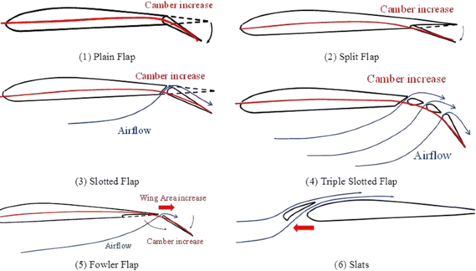
Mechanical high-lift devices.

The pressure distribution around airfoil is improved and CL is increase by this device.
-
Split Flap As shown in Figure 3(2), this devise mechanism is resembled with the plane flap. However, the sprit device is only bended the lower side of the trailing edge.
-
Slotted Flap As shown in Figure 3(3), a flap increase a camber angle and make a space said as slot between main part of the airfoil and the flap. By leading the high pressure flow slot from under the airfoil to the upside the airfoil through the slot, the peeling air flow in the trailing edge area is prevented and CL is increase.
-
Triple Slotted Flap As shown in Figure 3(4), the small airfoil with high camber is provided between the main airfoil and the flap. This small airfoil is said as vane. There are 3 sections of slots.
-
Fowler Flap As shown in Figure 3(5) this flap mechanism has two deformation and two effects. Firstly, the flap is moved almost to the rear, to increase the lift by increasing the wing area. Secondly, further flap is moved to the rear, it is bend in downward at the same time. In addition by increasing the camber angle with increasing the wing area, to increase the lift.
Effectiveness of these derives from the increased camber of the airfoil section. High camber increases the maximum lift coefficient. In addition, fowler flaps and slotted flaps can slightly increase the wing area, thereby increasing the lift. However, the trailing edge flap cannot prevent the separation of the flow around the wing. In fact, because of the increase in circulation around the wing, the increase in upwash at the leading edge makes the flow separate more easily and reducing the separation angle. Furthermore, the increase in airfoil camber causes an increase in drag at low angles of attack, worsening the L/D ratio.
The second is the separation delay type, e.g. slats as follows:
-
Slats As shown in Figure 3(6), The part of the airfoil in leading edge side is separated in order to provide a space as said slats between flap and main airfoil. The high pressure air thorough the slats to upside of airfoil form under side. This flow leading is help to prevent the peeling of airflow. Therefore, stall angle and Max CL are increase.
The flow separation around the wing is caused by a negative pressure gradient and loss of kinetic energy because of viscosity. By using slots and slats, the leading edge of the wing is shifted forward to create a gap, through which the flow underneath the wing is guided to the top surface. By adding momentum to the trailing edge flow, the flow can be prevented from separating and lift can be maintained at high angles of attack. However, slats and slots require flight with a high angle of attack to generate high lift [5].
Boundary Layer Control
Static control high-lift devices
-
Vortex generator This device uses the property that turbulent boundary layer to the flow is not easily peeled off than the laminar boundary layer. The projection on the airfoil surface forcibly transition boundary layer from laminar flow to turbulent. This projection is said as the vortex generator [6]. At high angle of attack, the effect of increasing the stall angle. However, at low angle of attack, projections increase the drag and exacerbate the high-speed performance.
Active control high-lift devices
Active control high lift devise is also said powered high lift device. Powered high-lift devices operate through control of the boundary layer. Because momentum is directly added to the boundary layer, airfoil performance in the high Reynolds number region can be easily realized artificially [5].
-
Suction and/or blowing High lift is obtained by adding momentum to the wing surface boundary layer by means of suction and/or blowing. Conventionally, suction and/or blowing utilizes the engine exhaust flow or a compressor driven by the engine. Therefore, it is expected that the effect of suction/blowing is not worth the weight increase because electrically powered SUAVs don’t have an engine exhaust, making it necessary to mount an additional motor for the compressor.
-
Magnus effect In an alternative design, a rotating cylinder wing providing lift by the Magnus effect has been studied [7]. A rotating cylinder in the leading edges of the airfoil [8] has also been developed. However, very few devices using the Magnus effect have been operated successfully [9].
-
Vibration type As shown in Figure 4, the high lift device has small size Electromagnetic actuators on the upside surface of the airfoil in the leading edge [10]. Each actuator generates the vibration in vertical direction to the airflow direction in order to add the momentum to the airflow of upside surface of the airfoil. In case of high angle of attack, the device provides to increase the stall angle by 3° and Maximum CL by 25%. However, this device needs a lot of actuators, the mass increase is a challenge to the practical design.
Figure 4 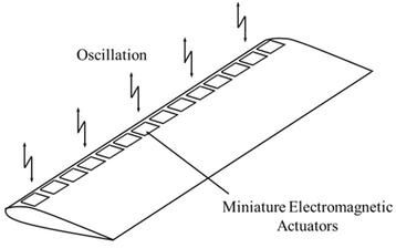
Miniature Electromagnetic Actuators on the Wing.
-
The Sound wave type This high lift device improves the aerodynamic characterstics of the airfoil by utilizing properties such as prompting the reattachment of laminar separation by an acoustic excitation vibration [11]. This device system is as follow. The speakers of sound source are placed around the wing as shown in Figure 5. The sound wave (pressure) is provided toward the wing. The L/D is increased then the ordinary airfoil. However, the speaker must be placed above the surface of the airfoil. It is a challenge to the practical design.
Figure 5 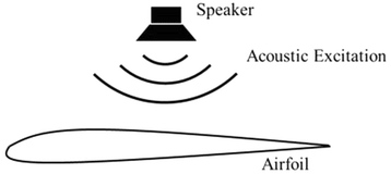
Reattachment of Flow by Acoustic Excitation.


Present challenge
Although various types of high-lift devices have been proposed and employed thus far, none are truly appropriate for SUAV systems, especially in the low Reynolds number region. It is not practical to add blowing or suction if the SUAVs are powered electrically. Therefore, a powered high-lift device of SUAV is needed to compensate for the lack of lift by simple system when takeoff, landing and lifting the nose rapidly.
Methods
When applying a high-lift device to an SUAV, the design requirements listed below must be considered, and a mechanism to compensate for the drop in L/D in the low-speed region is proposed accordingly.
Design requirements
The following three design requirements are important when applying high-lift devices to an SUAV.
-
(1)
The additional weight of the mechanism must be minimized to retain the maximum possible payload capacity.
-
(2)
The mechanism must be simple.
-
(3)
The mechanism must enable a high L/D ratio at a low angle of attack.
Among the high-lift devices discussed in Section Types of high-lift devices, the powered type is considered most suitable for an SUAV. This is because in the Reynolds number range under consideration, the airfoil performance will drop regardless of the airfoil shape. Thus, the airfoil shape change caused by flaps and other devices is expected to have only a small effect. In addition, the operation of a flap will cause an increase in drag at low angles of attack, which is undesirable from the viewpoint of reducing the L/D ratio. Similar arguments could be made regarding slats and slots: making it difficult to increase the L/D ratio at low angles of attack. Therefore, powered high-lift devices have been used in this study. The long distance operation of SUAVs is not essentially different form passenger aircraft. The situations where high-lift devices are usually required are: takeoff, landing, and lifting the nose rapidly. Therefore, using a powered high-lift device to compensate for the lack of lift by simple system when can be expected to reduce the size of the SUAV. Thus, mounting one or more actuators becomes a prerequisite. To satisfy conditions (1) and (2), the number of actuators and their weight should be minimized. To satisfy condition (3), momentum must be added to the flow around the wing, regardless of the angle of attack.
Proposed mechanism and its effect
In light of the abovementioned considerations, the following mechanism is proposed. As seen in Figure 6, a belt is laid out at the top and bottom of the wing; this belt is driven by a single motor and pulley positioned at the leading edge of the wing. This mechanism is superior to other methods such as suction and/or blowing because the number of actuators and their weight can be minimized, and the momentum is added to the entire wing surface via a simple device. Therefore, requirements (1)–(3) are expected to be satisfied. When applying the proposed mechanism, the following two effects are anticipated:

Concept of circulation-controlled high-lift wing.
-
(i)
An increase in the L/D ratio
-
(ii)
A delay in flow separation
From the no-slip condition, the speed of the flow around the wing increases in the direction of the belt, thereby increasing the circulation around the wing. This increases the lift. Because there is no impact on the frontal area of the wing, the increase in drag is small when compared to the flap method (for example). In addition, the L/D ratio is expected to increase at low angles of attack, and furthermore, the addition of momentum through the belt prevents flow separation at high angles of attack, thereby maintaining lift. In other words, active lift adjustment can be performed by controlling the belt rotation speed.
Results
Validation of proposed mechanism
To validate the effects described in Section Boundary Layer Control, a wind tunnel test was conducted for the belt-driven wing and the non-driven wing, both of which had the same airfoil shape. The measuring ranges of angle of attack are until stall angles.
Experimental wing
The experimental wing geometry is shown in Figure 7. The GOE478 airfoil was chosen because of the ease of measuring the lift under the non-driven condition, its relatively high lift coefficient at low Reynolds numbers, and its simple shape. A rectangular wing was chosen to make it easy to implement the belt drive mechanism.

Experimental wing.
The chord length was set at 160 mm with actual flight conditions in mind and with the aim of generating a Reynolds number Re of ~105 at an airspeed of 10 m/s. The wingspan was set at 226 mm (drive section: 200 mm) considering the dimensions of the low-speed wind tunnel (measurement section: 500 mm × 500 mm). If the airspeed is over 10 m/s with same wing model, the Reyonlds number is bigger than 105. In this condition, ordinary wing can provide high L/D as other passenger plane. In other words, high lift devices are not need in this condition. Therefore, we did not conduct with other than 10 m/s (Re =105). A belt made of polychloroprene on the drive surface was used, and it was driven by a motor positioned on the side. The belt could be driven at a maximum speed of 32 m/s. Because it is not possible to bend the leading and trailing edges using a pulley, the drive area was limited to the range shown in Figure 7. To replicate the two-dimensionality of the airfoil, wing end plates (150 mm × 300 mm) were placed at both ends of the airfoil. The belt surface of the device is smooth as same as ordinary wing model surface in order to independently analyze the high lift effect by the belt speeds. It is expected to enhance the high lift effect by adding the fun patterns on the belt surface. In addition, fun patterns are expected to add momentum for the longitudinal direction of wing surface flow too. The improvement of attached fun patterns on the belt surface will be studied in future works.
Experimental conditions
With the airspeed of the wind tunnel fixed at 10 m/s, two different belt speeds (10 and 20 m/s) were tested. The lift and drag were compared for the belt-driven and non-driven wings under these conditions. The measuring ranges of angle of attack are until stall angles. Under these conditions, the Reynolds number was 1.1 × 10⁵.
Experimental results
The experimental results are shown in Table 1. Figures 8, 9 and 10 show the lift, drag, and L/D curves, respectively. For an angle of attack of 0°–7°, a 10 m/s drive speed showed the highest lift coefficient; for a higher angle of attack, the 20 m/s drive speed showed the highest lift coefficient. At low angles of attack, the drag coefficients were similar regardless of the drive speed, but at high angles of attack they showed a minor increase with drive speed. The highest L/D ratio was 117 at a drive speed of 10 m/s, which was 1.67 times higher than that of the non-driven wing (69.8). At drive speeds of 10 and 20 m/s, a high L/D ratio was maintained even in the angle of attack range that caused stall in the non-driven airfoil case. While the stall angle for the non-driven airfoil was 11°, the belt-driven airfoil showed significant improvement—the stall angles were 23° and 28° for 10 and 20 m/s conditions, respectively.

Lift curve.

Drag curve.

Lift-drag ratio curve.
Thus, the mechanism was confirmed to produce an increase in L/D ratio in low angle of attack and a separation delay. It means this device meets to the design requirement (3).
Discussion
In this paper, we only conducted the experiment with one wing shape. In addition, both specs of SUAV such as wing size and the purpose of use are variety. Therefore, to decide the best angle of attack and belt speed is difficult. We discuss the trend of performance of the device. As prerequisites, the angle of attack is constant and small when the SUAV cruises. The SUAV can cruise and keep ground height with stopped the high lift device. We discus about better angle of attack and belt speed when SUAV take-off, land and ascend. As shown in Figure 10, In order to increase L/D, the methods are needed to keep the device speed at 10 m/s and to increase the angle of attack until the angle of attack is 7°. In case that angle of attack is over the 7°, the belt speed is needed to increase such as 20 m/s. To assume the taking off task, the recommended operations are as follows. The belt speed is set as the target flight speed. 2) To accelerate the thruster with constant flap angle, the SUAV get the enough lift to take off with heavy payload, In this case that the flight speed and belt speed is the same, the SUAV can fly robustly under the strong wind because the lift is slight change by angle of attack change. On the other hand, the belt speed is needed faster than the flight speed when chandelling with large angle of attack or ascending with constant flight speed and angle of attack.
Flow visualization
To confirm the flow separation delay visually, a flow visualization test was conducted by using the smoke-wire method. In this experiment, it is possible to understand more detail of effect of using the device.
Experimental conditions
Visualization by the smoke-wire method was conducted for angles of attack starting at 0° with 5° increments. The test conditions are shown in Table 2. In addition, for more visualization experiments in high angle of attack, low speed experiment (Re = 3.2 × 10⁴) with blue laser were also conducted.
Experimental results
-
(1)
α = 0°
In case that the angle of attack is 0° with 10 m/s mobbing belt in Figure 11(1), the flow upon the airfoil is acceraleted than the ordinary airfoil model. The momentum is efficiently added to the flow upon the airfoil by the moving belt. On the other hand, in case that the belt speed is 20 m/s, the flow around the air foil is disturbed. Under the airfoil, belt moving direction is opposite direction to the airflow. The peeling shear layer is assumed to occurs under the airfoil by these air flow collide. In other words, in case that belt speed is considerably faster than the flight speed with small angle of attack, the CL is decrease than in case of belt speed is near the flight speed, because the effect of the momentum added to the flow upon the airfoil is smaller than the side effect of the pressure rise by the peeling shear layer under the airfoil.
Figure 11 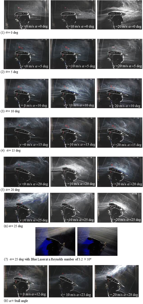
Flow visualization.
-
(2)
α = 5°
The results for α = 5° are shown in Figure 11 (2). The CL at the belt speed 10 m/s and 20 m/s are 1.51,1.32.
These differences are decrease than in case of angle of attack 0°.
However, in case of 10 m/s is larger CL than 20 m/s. It is assumed to effect by the peeling shear layer under the airfoil.
-
(3)
α = 10°
The results for α = 10° are shown in Figure 11(3). When the airfoil surface was not driven, flow separation could be observed at around 25% chord length. In case of v = 20 m/s, the air flow is smother than in case of v = 10 m/s. In particular the different is appeared in trailing edge. This result is assumed that the air flow speed upon the air foil is faster than 10 m/s and near the 20 m/s due to increase the angle of attack. Therefore, the momentum adding by 10 m/s belt is Insufficient and the momentum adding by 10 m/s belt is effective.
-
(4)
α = 15°
The results for α = 15° are shown in Figure 11(4). When the wing surface was not driven, flow separation could be observed immediately after the leading edge. When the surface was driven, flow attachment was observed toward the trailing edge.
-
(5)
α = 20°
The results for α = 20° are shown in Figure 11(5). When the wing surface was not driven, permanent flow separation from the leading edge was observed. When driven, flow attachment was observed toward the trailing edge.
-
(6)
α = 25°
The results for α = 25° are shown in Figure 11(6). When the wing surface was not driven and driven at 10 m/s. As the drive speed was20 m/s, the flow attached to the wing surface, the flow was confirmed to be securely attached all the way to the trailing edge. In addition, the flow difference between in case of 10 m/s and 20 m/s was shown in the experiment with blue laser at a Reynolds number of 3.2 × 10⁴ in the Figure 11(7)
-
(7)
α = Stall angle
The results with the stall angles are shown in Figure 11 (8). When the wing surface was not driven with angle of attack 12°, the flow separation is slightly shown in the trailing edge area. With the further increase in angle of attack the angle, the flow separation zone grew up to the leading edge direction, and gradually CL decreased. Therefore, stall type is a trailing-edge stall type. Similarly, in case of the wing driven at 10 m/s, the flow separation was growing up from the trailing edge area toward the leading edge area. Therefore, stall type is same a trailing-edge stall type. On the other hand, in case of the wing driven at 20 m/s, airflow was suddenly separating from trailing edge to leading edge on the same timing in attack angle 28°. At an angle of attack 28°, the lift force is almost not generated. The stall characteristics are similar to the leading-edge stall type. However, features with driven at 20 m/s is that the drag was not increased rapidly. By the high-lift device, the cause is considered that the portion of the airflow are flowing without separating.

From the results, this device is capable of assisting in situations where the aircraft takeoff or land with low speed and a large angle of attack. The improving the stall characteristics that are increased robustness to changing of angle of attack by wind. It is contributed practical applications. In addition, this device increases the payload and produces a short-range takeoff and landing. A further example of potential operational advantages is the possibility of suddenly reducing the lift by stopping the belt rotation, or reverse drive.
Design feasibility of SUAV with circulation-controlled high-lift wing
The Design requirements in order to apply the high-lift device to an SUAV were described on Section Design requirements. The implementation method about the requirement (3) was shown in previous section. In this section, the requirement (1) and (2) are discussed. Firstly, the requirement (1) is a compromise between the device weight and high lift effect. The device weight is strongly depended on the battery size needed to a task of sUAV. A estimate of the battery size assumed the real operation is requreird. This is described in Section The amount of extra battery for the task of sUAV. Secondly, the requirement (2) is a feasibility of mechanism. In order to clarify to meet the requirement (2), we prototype the device for sUAV. This is described in Section The mechanism design of the high lift device to SUAV.
The amount of extra battery for the task of sUAV
The purpose of this device is to maintain sufficient payload capacity of sUAV in Re of ~105 situation to install such as communication devices and observation equipment. For example, an observation task by sUAV with heavy sensing system. Hence, the high lift device is not needed to the satiation (task) witch ordinary sUAV can conduct.
-
A.
The High lift device is only used in the situation that lift is insufficient. For example, take off and chandelle. We estimated the battery size assumed the take-off. If the SUAV take off and ascend with 10° angle and 10 m/s to 200 m ground height, the SUAV need about 2 minutes. As the target performance is set as 5 minutes with a margin.
The battery size need to 5 minuites by the motor of the high lift device wing model with 20 m/s belt speed is about 450 mAh( 11.1 V). This size Li-Po battery weigh is about 40 to 50 g.
The mechanism design of the high lift device to SUAV
We prototyped the device for SUAV in order to clarify to meet the requirement (1) and (2). We have developed an SUAV with a circulation-controlled high-lift wing, as shown in Figure 12. At wind tunnel test, the chord length of wing model was set at 160 mm and the wingspan was set at 226 mm in order to fit for wind tunnel measurement section size and set the Re number as 105. On the other hand, wing size of SUAV is not limited by the wind tunnel, the high lift device were installed in the general wing shape as shown in Figure 12(a). We plan to change the wing shape to enhance the high lift effect in future works. This SUAV was made from a radio-controlled aircraft. The total mass increase is 163 g and details as shown in Table 3. The main wing has a high-lift device and an aileron. The belts of the high-lift device are driven by a single shaft and motor, as shown in Figure 12 (b). We have estimated the increase in the payload of the SUAV due to the high-lift device. For this comparison, both aircrafts fly at an air speed of 10 m/s, the drag of their wings is the same, and the belts of the device are driven at 10 m/s. In this case, the maximum high-lift effect is expected to be ~1.67 times higher than that of the normal airfoil as shown in Figure 8. In addition, if the normal lift is 0.75 kgf, which is the same as the weight of the normal aircraft, the increase in payload is expected to be 340 g excluding the increase in weight owing to the high-lift device. Hence, realistically, the proposed device is expected to increase the payload of the SUAV. In the future, we will conduct flight tests and wind tunnel tests to further explore this issue.

SUAV with circulation-controlled high-lift wing.
As described above, the prototyping met to the requirement (1) and (2). In other words, design feasibility of SUAV with the high lift device is clarified.
Conclusion
The proposed system was validated by conducting a full-scale wind tunnel test and a flow visualization test, as described in Sections Validation of proposed mechanism and Flow visualization. It was found that the L/D ratio increased at low angles of attack and that a separation delay occurred at high angles of attack. Furthermore, the proposed system could maintain L/D for a wide range of angles of attack even in the low Reynolds number range where a conventional fixed airfoil stalls. Finally, it can safely add momentum to the flow around the airfoil without adding much weight. The last point, in particular, is very important for realizing a high-lift device for SUAVs that fly in the low Reynolds number range. The proposed system should quite feasibly find various practical applications and it should expand the application range of SUAVs. It is an important future task to verify the effectiveness of the proposed method by conducting flight tests.
References
Austin R, U Unmanned aircraft systems: UAVS design, development and deployment (Aerospace Series), (2010), pp. 1–8. Wiley. http://as.wiley.com/WileyCDA/WileyTitle/productCd-0470058196.html
Tang VD, Lian J, Liu Y, Shyy W (2006) Flapping and flexible wing aerodynamics of low Reynolds number flight vehicles. In: 44th AIAA Aerospace Science Meeting and Exhibit. http://deepblue.lib.umich.edu/bitstream/handle/2027.42/76905/AIAA-2006-503-331.pdf?sequence=1
Callaghan JG, Beatty TD (1972) Theoretical Method for the Analysis and Design of Multielement Airfoils. Journal of Aircraft 9(12):844–848. http://arc.aiaa.org/doi/abs/10.2514/3.59084?journalCode=ja
Mohammad H. Sadraey, Aircraft Design: A system Engineering Approach, ISBN: 978-1-119-95340-1, pp. 230–235, WILEY (2012). http://as.wiley.com/WileyCDA/WileyTitle/productCd-1119953405.html
Nicolai L. M. and Carichner G. E., Fundamentals of aircraft and airship design: aircraft design (AIAA Education Series). Amer Inst. of Aeronautics, (2010), pp. 222–253. http://arc.aiaa.org/doi/book/10.2514/4.867538
Bragg MB, Gregorek GM (1987) Experimental study of airfoil performance with vortex generators. Journal of Aircraft 24(5):305–309
Sanjay Mittal amd Bhaskar Kumar (2003) Flow past a rotating cylinder. J Fluid Mech 476:303–334
Reid EG (1927) Tests of rotating cylinders: National Advisory Committee for Aeronautics, Technical Note No. 209
Seifert J (2012) A review of the Magnus effect in aeronautics. Progress in Aerospace Sciences 55:17–45
Mamoru IKTKS, Takeaki O (2009) Stall Control of a Symmetric Airfoil by Means of Miniature Electromagnetic Actuators(Fluids Engineering). Transactions of the Japan Society of Mechanical Engineers, Series B 75(752):683–690
Iwai Y, Abe H, Kikushima Y, Aoki H, Kato E (2007) Improvement of Aerodynamic Characteristics for Airfoil by Acoustic Excitation. In: Proc. of Symposium on Environmental Engineering., pp 85–88
Author information
Authors and Affiliations
Corresponding author
Additional information
Competing interests
The authors declare that they have no competing interests.
Authors’ contributions
All authors equally contributed. All authors read and approved the final manuscript.
Rights and permissions
Open Access This article is distributed under the terms of the Creative Commons Attribution 4.0 International License (https://creativecommons.org/licenses/by/4.0), which permits use, duplication, adaptation, distribution, and reproduction in any medium or format, as long as you give appropriate credit to the original author(s) and the source, provide a link to the Creative Commons license, and indicate if changes were made.
About this article

Cite this article
Yamada, Y., Vasilieva, I., Takayama, A. et al. Circulation-controlled high-lift wing for small unmanned aerial vehicle. Robomech J 2, 8 (2015). https://doi.org/10.1186/s40648-015-0031-1
Received:
Accepted:
Published:
DOI: https://doi.org/10.1186/s40648-015-0031-1